Analysis
Project Requirements
The balsa wood bridge must span 400mm while supporting 18.9kg and deflect less than 25mm from horizontal.
The total weight of the bridge must not exceed 85 grams (not including articulating parts).
The bridge road deck shall be free of obstructions such that a 32mmx20mm block can pass over the length of the road deck at a constant rate.
The bridge must raise mechanically 140mm above the horizontal with a deflection less than 25mm.
When 10g of force is applied the bridge will raise enough so that a piece of 20lb printer paper can be slid beneath it.
The bridge will only be constructed of balsa wood and wood glue.

Analysis 1
For Analysis 1 some forces were calculated on the bridge members to ensure that the bridge will satisfy the requirement of holding 20kg. This analysis will prove if the assumed dimensions will meet the load requirement. After calculations it is determined that the bridge will fail at 20kg, and the design needs to be reworked in order to find a design that fits the requirements. This will be done by increasing the amount of members to add strength by distributing the load. It will also be noted that properties of American Balsa wood were recorded in this lab from Matweb.com.
Analysis 2
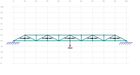
Analysis 2 was still focused on the 20kg weight requirement to be supported by the bridge. Duing this analysis a truss program in MDsolids was used to calculate the forces and stresses on the bridge’s main span. This was a useful way to double check the hand calculations previously made. According to hand calculations, and the calculations done by MDsolids, a force of 98N was found to be on supports B and D. These calculations do not consider that the bridge is 3D, therefore, since the bridge has another symmetrical half in the z-direction, it can be assumed that the actual exerted force will be half the calculated force. This calculates to 49N, a reasonable value for the member to support& more. This analysis was useful because it determined that the bridge dimensions will satisfy the 20kg load requirement.

Analysis 3
Analysis 3 is still focused on meeting the 20kg load requirement. For this Analysis the goal was to start to solve by hand the different reactions happening on the bridge members. Specifically this analysis solved for the support reactions on both ends of the bridge using static equations of equilibrium. These were found to be 98N in the Y direction. This satisfies the bridge requirements and was a useful analysis to show that the design can continue to progress and a part can be made from the dimensions in the bridge calculations.
Analysis 4
In the previous analysis it was determined that there will be support reactions of 98N, this value will be split in half to account for the bridge being 3 dimensional, while the 98N value is for a two-dimensional truss analysis. Using a reaction force of 46N, and a truss length of 5cm, the modulus of rupture was calculated for this lab. This calculated value turned out to be 120kPa, while the maximum modulus of rupture American Balsa wood can withstand is 21.6GPa. This results in the design parameter of 5cm in between truss’s to be valid and satisfy the support requirement of 20kg.

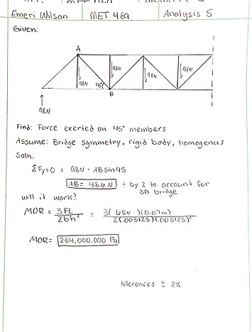
Analysis 5
The design requirement that was studied in this analysis was the ability to support the 20kg load specifically in the 45-degree truss members with a length of 70.7mm. It was found through summing the forces in the Y-direction that the 45-degree trusses would experience a force of 68N and that they would be in tension. This is an acceptable loading value for this material and proves that the design parameter of the 70.7mm truss at 45-degrees is a suitable member in the bridge. This Analysis resulted in the drawing of this truss member, located Appendix B. See hand calculations in appendix A-5.
Analysis 6
Still basing off the 20kg load requirement, this analysis was focused on the 50mm members spanning horizontally in the bridge. For this analysis through the use of trigonometry, it was found that the 50mm members would be subject to a force of 96N. The 50mm members on the bottom of the bridge would experience that force in compression, while the members on top of the bridge would experience it in tension. Both were found to be suitable loads for the given members, proving that the 50mm truss satisfies the load requirements. Due to this analysis, a drawing of the 50mm member was developed and is in Appendix B. See also Appendix A-6 for raw calculations as well.


Analysis 7
Analysis 7 was based off the design requirement that the bridge must articulate 140mm in the vertical direction. To do this, the design solution was to make use of a small cable to lift the bridge. Analysis 7s purpose was to calculate the strength of a cable like material to see if the cable would support the bridge’s weight. This was done by first selecting a material. Middle weight thread in the size 60/Tex 70 was chosen for its availability and cost. It was found that this thread has a tensile strength of 11bs, well over the required 85g for the thread to lift. This cable material meets the requirements for lifting the bridge. See Appendix A-7 for calculations.

Analysis 8
Analysis 8 was based off the requirement must articulate 140mm in the vertical direction. To do this, the design plan is to build 2 columns on each side of the bridge that the pully system will attach to that will hoist the bridge the 140mm. The structural integrity of these columns must support a minimum of 85g. The smallest member in the column's measures 50cm. This analysis will prove that the smallest membered section will be able to support those 85g. This was done by calculating the modulus of rupture of the 50cm section and then comparing it to the modulus of rupture required to break American Balsa wood. It was found that the MOR (Modulus of Rupture) on the 50cm section was below that of the MOR required to fail. Therefore, proving that the 50cm member will not fail while subjected to the lifting forces of the bridge. See Appendix A-8 for calculations and Appendix B-6 for resulted drawing in support member.
Analysis 9
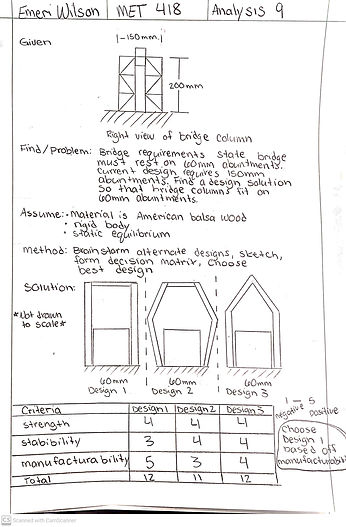
Analysis 9 was focused on the requirement that the bridge must rest on 60mm abutments. This requirement was overlooked in the initial design of the bridge columns that would support the lifting mechanisms. In the original design, the bridge requires 150mm abutments. To satisfy the design requirement, three redesigns of the bridge column were created. Using these three designs, a decision matrix was formed to choose the best design that would satisfy the requirement of resting on the 60mm abutment. The designs were judged based off how stable they were, how easy they would be to manufacture, and how strong the design was. The decision matrix yielded two results, and from the two, design one was chosen due to it would be easier to manufacture. See Appendix A-9 for calculations.
Analysis 10
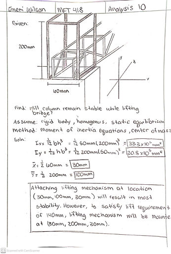
Analysis 10 was focused on the requirement that the bridge must articulate 140mm upwards. To satisfy this requirement a design was decided upon in the previous analysis that was most suited for the job. Calculations were then done on this design to find the optimal location of mounting the lifting mechanism to keep the structure stable. This was done by finding the moment of inertia as well as the center of mass for the design. It was found that the optimal location to attach the lifting mechanism was at the Y-location 100mm. This would not satisfy the 140mm lift requirement, so it was decided that the lifting mechanism will be placed on the Y-location of 200mm. This will not be as stable as the y-100mm location, but since this aspect of the design will not be load bearing, it can be assumed it will remain stable and two drawings resulted from this analysis can be created, see Appendix B-7-8 for drawings. See Appendix A-10 for calculations.
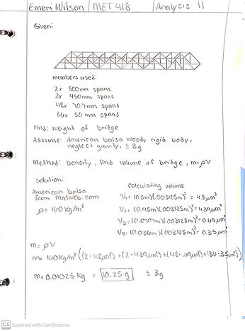
Analysis 11
HeadAnalysis 11 dealt with the requirement that the bridge must weigh under 85g. To see if the current bridge design would satisfy this requirement, its weight was calculated. To do this first the bridges volume was calculated by finding the volume of each member and then summing them. Once the total volume was found, this value could be multiplied by the density of balsa wood found to be 160 kg/m^3 on matweb.com. The final value comes out to be 0.01025kg, or 10.25g. This is well under the weight requirement and allows for the bridge to have weight added to reinforce the structure. See Appendix A-11 for calculations.
